|
Introduction
An experimental apparatus to measure the angular vibrations on a rifle barrel has been described elsewhere. This article describes an attempt to create a computer model of the vibrations on a rifle barrel - or more particularly, on a rimfire rifle barrel. Many references to vibrations on a rifle barrel cite the analytic equation of motion for transverse vibrations on a beam, particularly the natural frequencies as derived for the boundary conditions of a cantilever, which is a "fixed-free" beam. There are two problems with this approach. First, if it assumed that the vibrations on a rifle barrel will be driven by the moment exerted on its back end due to the recoil forces rotating the rifle about its centre of gravity, (which is invariably below the bore-line), this means that setting the back end of the barrel as "fixed" for a boundary condition - so unable to move at all - is clearly a nonsense. A much better model would be a "pinned-free" beam. But secondly, the time frame of interest is the first few milliseconds when the bullet is still in the barrel. Now, the transverse vibrations on a barrel are phase-waves which travel much slower than the speed of sound in the steel of the barrel. This means that it takes many tens of milliseconds for the broad frequency content of the impulsive excitation moment applied to the back of the barrel to be resolved into the natural frequencies of a vibrating beam. At which point, of course, the bullet will be well on its way down the range and past caring what the barrel is doing. An effective model for the vibrations on a rifle barrel will allow for a realistic description of the complex non-periodic driving moment at the back of the barrel, and will also give an adequate description of the behaviour of the barrel during the first few milliseconds after the excitation has commenced. There is no alternative but to create a numerical simulation as a computer model in an attempt to render this scenario. To this end, a lumped parameter computer model was created.
Results The green trace is the the change of angle at the muzzle with time as predicted by the lumped parameter computer model described above. The barrel was 600mm long and 25mm in diameter. The barrel was modelled by dividing it into 20 elements, each 30mm long. The assumed excitation source for the vibrations was an impulsive moment applied to the back end of barrel, due to the recoil forces attempting to rotate the rifle about its centre of gravity, which is normally below the bore-line. The time history of this moment was assumed to match that of the bullet acceleration in the bore as a function of time. This will be very similar to the static pressure-time curve in the chamber, but will fall away somewhat more quickly on the trailing edge, and have a half-width of about 0.3 milliseconds.
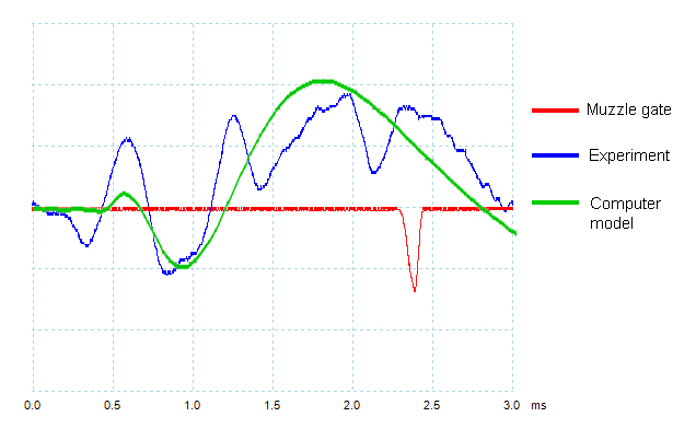 The green trace of the model output has been scaled to match the amplitude of the experimental displacement at around 1 msec. For the period earlier than 1 millisecond, the general direction of the displacement with time is in good agreement with experiment, though the amplitude is low compared to experiment. Due to the dispersive nature of the phase velocity for the transverse vibrations, the higher frequencies resulting from the impulsive moment applied to the back end of the barrel will arrive at the muzzle first. As explained in the description of the model, higher vibrations will be progressively damped as their frequency approaches the critical damping frequency, the period of which for this scenario will be about 0.12 msec. This will explain the low amplitude of the predicted vibrations earlier than 1 millisecond. For the period later than 1 millisecond, it will be seen that the model predicts the general nature of the angular displacement, but that there is a superimposed higher frequency element which the model does not predict. The origin of this higher frequency element is not presently understood, but in the experiment described above, it was shown that it is very important in the performance of a rimfire rifle.
Conclusions It should be noted here that a far more sophisticated approach by "Varmint Al" using a state-of-the-art full finite element analysis simulation of the whole rifle, also does not predict the high frequency component of vibrations generally observed on rimfire rifle barrels. It may be that the lumped parameter model used here may be applied more suitably to centrefire rifles, where the recoil forces are orders of magnitude higher, actions tend the be "stiffer" and the time periods of interest are shorter. However, the apparatus for measuring barrel vibrations described above is not currently suitable for use with centrefire rifles.
|