|
Introduction
Initial groups with Tenex WP439 using the reference barrel BB01 (bore .217", groove .222", 6 grooves, 16" twist, 26" long, SAAMI Match chamber, 0.041" headspace) in the test rig produced an average ESEE (Extreme Spread Edge to Edge) of around 13.5mm at a range of 50 metres. WP439 dates from the early 1990s and was the ammunition used to test rimfire rifles that we were rebarrelling at that time. Our acceptance criterion was that the rifle should be able to shoot 12mm ESEE groups at 50 metres when using the WP439 ammunition, and while the average group from barrel BB01 was a little larger than this, there were a number of groups less than 12mm ESEE. WP439 had been considered "one of the best batches of Tenex ever made" at the time and shot well in almost any rifle. By contrast, the new 'flat nosed' Tenex batch 1055, dating from this year (2010), shot considerably worse than this out of reference barrel BB01 producing around 15.5mm ESEE. These groups were disappointing. The test rig had been built to be a rigid 'barrel vice', but it was plain that bottom plate flexed due to the recoil force. When looking through the scope (attached to the top of the barrel clamp) the picture would 'jump' noticeably when the rifle was fired.
Groups with this free recoil rig were initially disappointing as they formed vertical strings. The barrel and action were indexed 90 degrees to the left and to then to the right, but the groups produced were always strung vertically. Any systematic problem with the barrel and action was thus ruled out as the cause of the vertical stringing. The cause may have been some property of the free recoil rig. But this seemed unlikely as, when looking through the scope attached to the top of the carriage, it was simply not possible to force the rig to flex anything like enough to shoot a vertical group of the extent seen on the target. The only possible answer left was that the vertical stringing was due to velocity dispersion in the ammunition. Slow rounds were dropping low and fast rounds had a flatter trajectory and resulted in the higher shots. Initial computations for a typical velocity spread of, say, 20 ft/sec., seemed to produce vertical dispersion of the order seen on the target. So it was decided to do further tests to correlate muzzle velocity with the vertical fall of shot on the target.
Experimental procedure Reference barrel BB01 was cleaned and a series of groups were fired using Tenex batch 1055. This was followed with a series of groups using Tenex batch WP439. As each 5 shot group was fired, a sketch of the group was made, carefully noting the position of the horizontal cross hair on the scope (which was fixed to the carriage) with reference to the group. When the groups were analysed, a line was drawn on the target where the horizontal cross hair of the scope had been observed. The distance of the centre of each shot from this line was measured and plotted on a graph as a function of its chronograph velocity.
Results
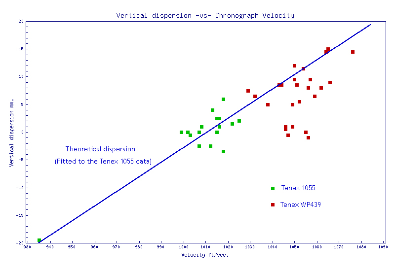
Theoretical velocity dispersion
Discussion The theoretical dispersion line was fitted by eye to the Tenex 1055 data only. An attempt to fit the line to both sets of data (Tenex 1055 and Tenex WP439) would assume that bullet ballistics of both sorts of Tenex were identical. It is clear that the average of the Tenex WP439 data sits a little below the line although parallel to it. This would be consistant with the argument that the old style round nosed bullet of Tenex WP439 has slightly more drag than the flat nosed bullet of the newer Tenex 1055. There is a cluster of six shots at around 1050 ft/sec. sitting within half a millimetre of zero relative dispersion. This data clump, which is made up of shots spread thoughout the data set, is clearly isolated from the rest of the data for Tenex WP439. The reason for the anomalous relative dispersion of these shots is unknown, but a possible cause is light changes above the sky screens of the chronograph. This does not explain why the cluster is around the particular velocity of 1050 ft/sec. and a relative dispersion of zero. But whatever mechanism caused this anomalous cluster, it is not thought to have affected the rest of the data. Discounting the anomalous group of data mentioned above, the fit of the data to the theoretical dispersion line slope are quite good. The observed scatter about the line of about ± 4mm would be what is expected if the centre-to-centre vertical group size due to random scatter was around 8mm. This was indeed typical of the group size that was being observed in the test rig
Conclusions The velocity spreads of the two batches of ammunition used in this test were about 25 ft/sec. for the modern batch of Tenex and about 45 ft/sec. for the older batch of Tenex. These velocity spreads are assumed to be fairly typical, but even assuming that the velocity spread in a batch of ammo was exceptionally good, say 15 ft/sec., that would correspond to a vertical dispersion of almost 4mm at 50 metres. Such a level of dispersion would account for roughly half the vertical dispersion of a good batch of ammunition if there was no positive compensation or "tuning" in the rifle or test gun. It has to be concluded that for a rimfire rifle to have any pretensions to accuracy, it has to have some degree of positive compensation to account for velocity dispersion. It should also be noted that many attempts to show a correlation between muzzle velocity and fall of shot on the target have not shown positive results. Such tests are usually performed using conventional target rifles or bench rest rifles, where free recoil allows the consequent rotation of the rifle about its centre of mass, which is usually below the bore line. On the basis of the tests reported above, it can be reasonably concluded that this rotation about the centre of mass is converted into rifle dynamics which usually result in some degree of positive compensation in such conventional rifles.
Rimfire rifles - the future This is not possible with rimfire rifles as handloading rimfire ammunition is not a practical proposition. For rimfire rifles then, the only way to maximise positive compensation at a given range is to "tune" the rifle to the ammunition - a far more difficult proposition as there are many more variables to contend with (the shape and weight distribution of the rifle and its components) and the effects of varying these is not usually linear. Varying the position of large weights attached to the end of the barrels has been a popular way to try and tune the rifle, but the effect on rifle dynamics of varying such "tuners" is complex and not easy to extrapolate. That is, moving the tuner one millimeter may reduce the group size slightly, but moving it one more millimeter may not reduce the group size even more. However, Finite Element Analysis (FEA) programs which can model the stresses and strains in complex structures such as bridges, planes and cars have become increasingly available for increasingly powerful home computers. Using FEA programs, it is possible to build virtual mathematical models of a rifle and compute the dynamics of the rifle under recoil. Here is an example of one such attempt to do just that. Are the predictions of such a mathematical model correct? Well of course, it will be necessary to do experimental tests on an actual rifle and see if the model which has been constructed to represent it does so accurately - or at least, usefully. Given that it does, it is confidently predicted that no manufacturer or builder of accurate rimfire target rifles will be able to resist using FEA models to finalise the design of their product. If the rifle is not "computer designed", it will not live with the products of competitors who can boast such an attribute.
|
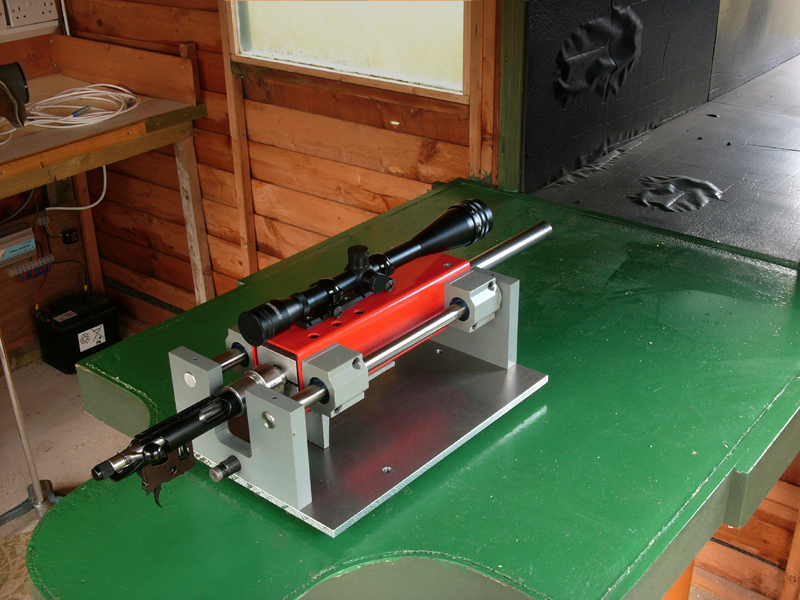 It was of concern that the recoil energy in the test rig was being dissipated in an unpredictable fashion into barrel vibrations that were affecting the group. In an effort to control the recoil energy in a predictable way, the Border Barrels Recoil Pressure Gun was adapted to make a free recoil test gun. With this gun, the recoil is constrained to be straight back, with the recoil energy being dissipated in friction by the linear slides on the rods and in the hydraulic damper seen at the back of the rig. The carriage is designed so that the centre of gravity of the recoiling mass is approximately on the bore line, so minimising any rotational moments when recoiling which might affect the launch angle of the bullet.